Trigger Using a PLC
Overview
This guide explains how to trigger the OV20i camera from a PLC over Ethernet/IP, monitor its status, and handle errors. The integration ensures reliable image capture within an automated process.
Prerequisites
- OV20i camera connected to the PLC (see Connect to PLC (Ethernet/IP, PROFINET)).
- PLC programming software (e.g., Studio 5000).
- PLC Trigger selected as the Trigger Settings in the recipe Image Setup
note
If PLC Trigger is not selected in the recipe, the camera will ignore PLC trigger requests.
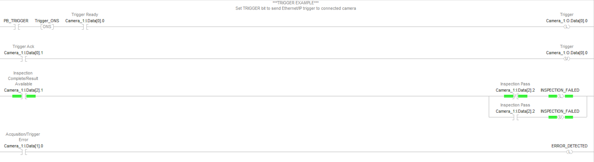
Logic Example
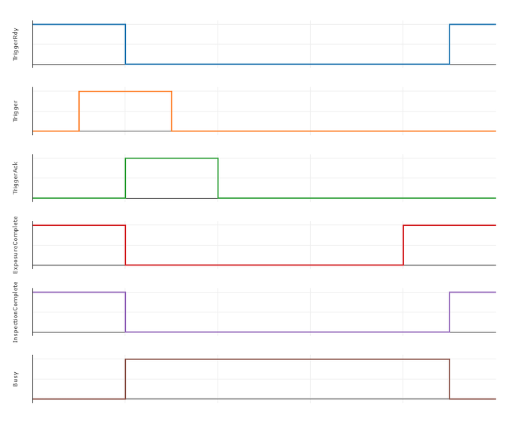
Timing Diagram
Core Concepts
Triggering the Camera
- PB_TRIGGER: Push-button or control signal from PLC logic to initiate capture.
- Trigger_ONS: One-shot that generates a single pulse on rising edge of PB_TRIGGER, preventing duplicate triggers.
- Camera_1:I.Data[0].0: Camera Ready — must be high before triggering.
- Camera_1:O.Data[0].0: Trigger Request — latched high until acknowledged.
- Camera_1:I.Data[0].1: Trigger Acknowledge — confirms camera received trigger.
Trigger Sequence
-
Confirm
Camera_1:I.Data[0].0(Ready) is high. -
Activate
PB_TRIGGER. -
Trigger_ONSpulses and setsCamera_1:O.Data[0].0(Trigger Request) high. -
Camera responds by setting
I.Data[0].1(Trigger Acknowledge) high. -
PLC unlatches
O.Data[0.0]to complete the trigger cycle.
Result Availability and Status
- Camera_1:I.Data[2].1: Result Available — high when image processed.
- Camera_1:I.Data[2].2: Pass/Fail Result — high = pass, low = fail.
Error Handling
- Camera_1:I.Data[1].0: Trigger Error — high if an error occurs during triggering.
- This bit latches until reset.
- Implement PLC logic to reset this bit and handle errors appropriately.
Best Practices
- Always check
Camera Ready (I.Data[0].0)before issuing a trigger. - Use one-shot logic (
Trigger_ONS) to avoid multiple unintended triggers. - Latch the Trigger Request until acknowledgment is received.
- Monitor result availability before reading Pass/Fail status.
- Implement robust error handling to detect and clear faults.
Summary of Key Signals
| Signal | Function | Notes |
|---|---|---|
PB_TRIGGER | Initiates camera trigger | From PLC logic |
Trigger_ONS | One-shot pulse | Prevents duplicate triggers |
I.Data[0].0 | Camera Ready | Must be high to allow trigger |
O.Data[0].0 | Trigger Request | Latched until acknowledged |
I.Data[0].1 | Trigger Acknowledge | Confirms trigger received |
I.Data[2].1 | Result Available | Image processed |
I.Data[2].2 | Pass/Fail Result | High = Pass, Low = Fail |
I.Data[1].0 | Trigger Error | Latched until cleared |
Conclusion
By implementing this logic, the OV20i camera can be reliably triggered and monitored using PLC control, ensuring accurate synchronization with industrial automation processes.